Leave your contact details and our
consultant will contact you
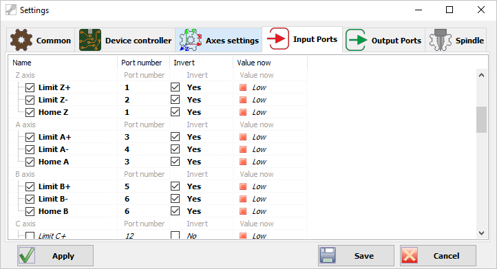
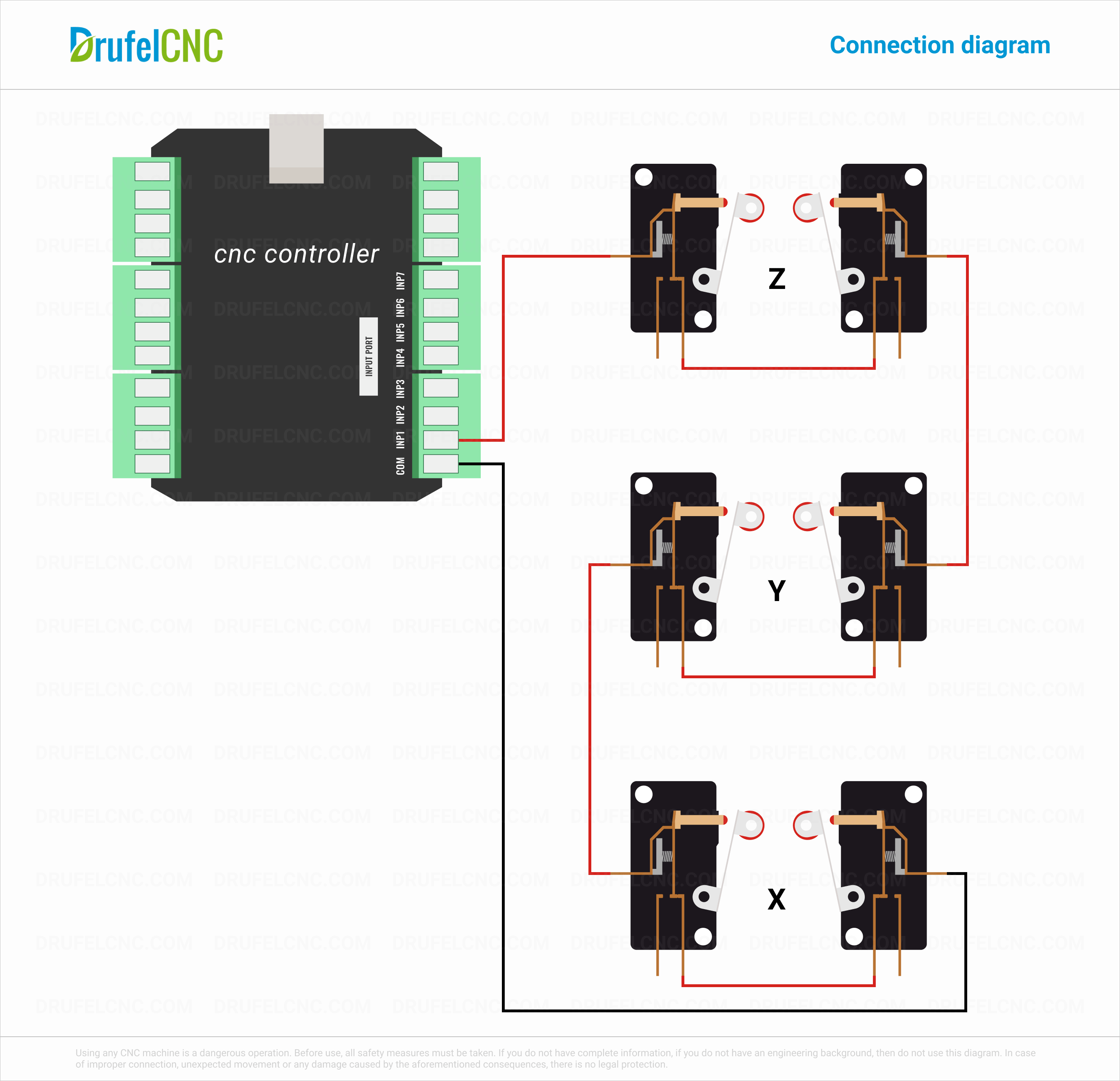
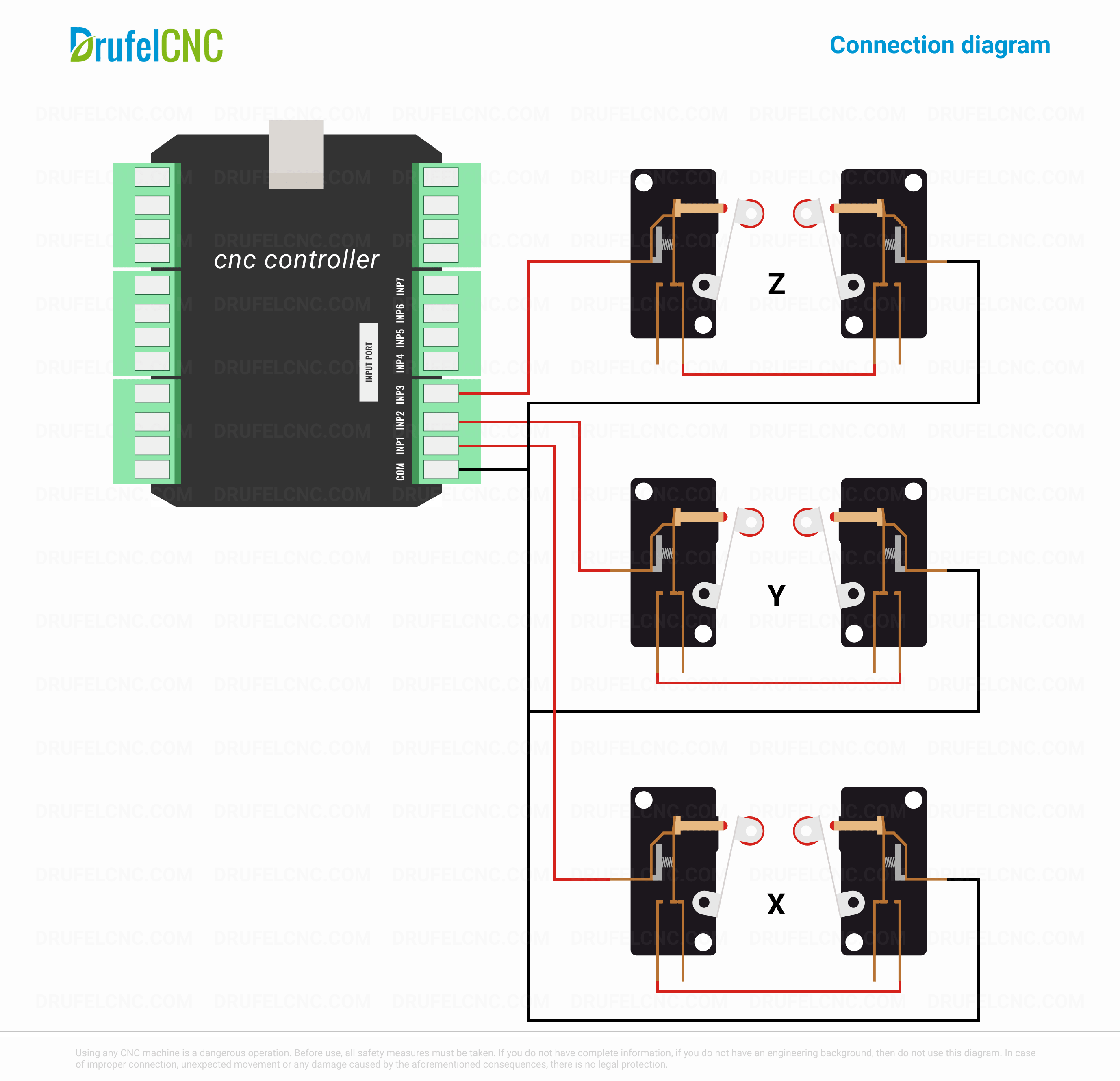
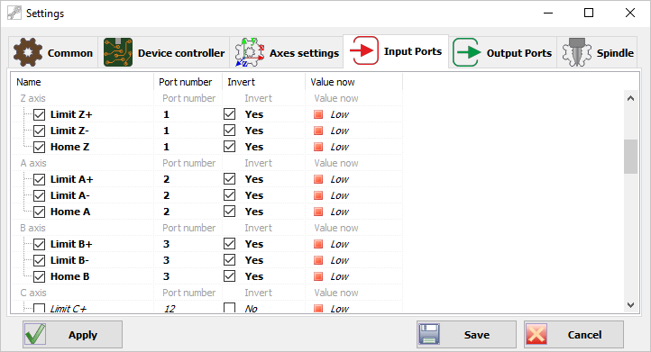
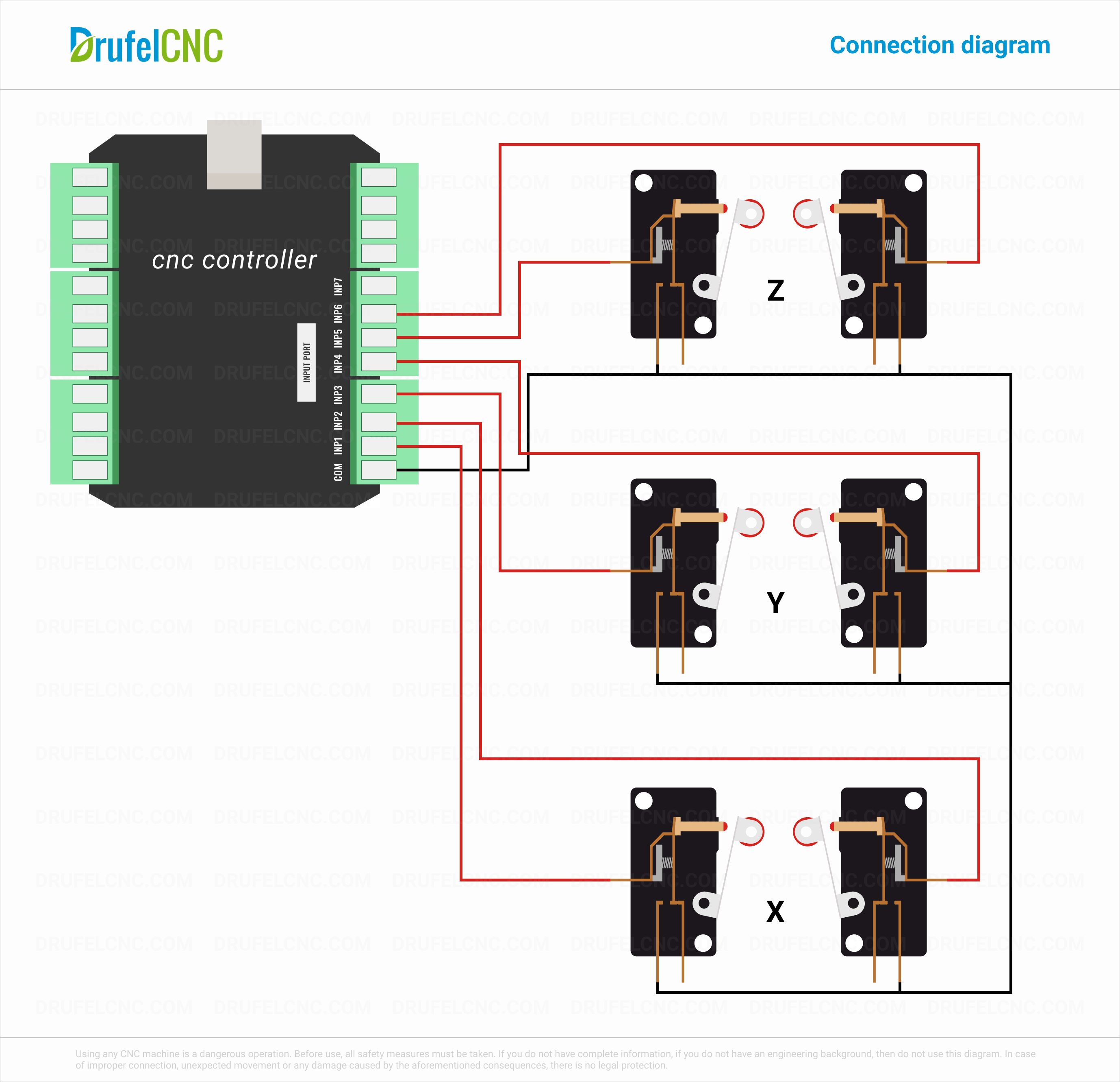
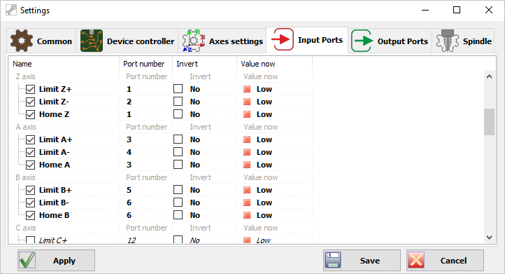
In CNC machines, limit switches are used to define the physical limits of the work area and to position the head to the homing position during the homing process.
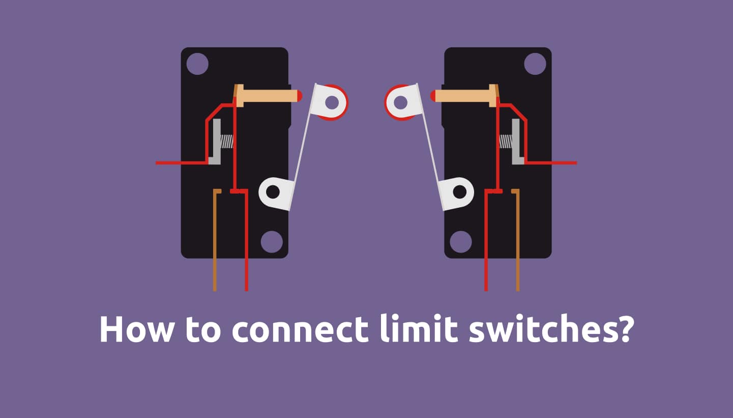
To connect the limit switches can be used normally closed and normally open circuit.
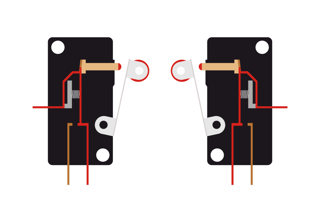
The picture shows the signal flow when the limit switches are not turned on.
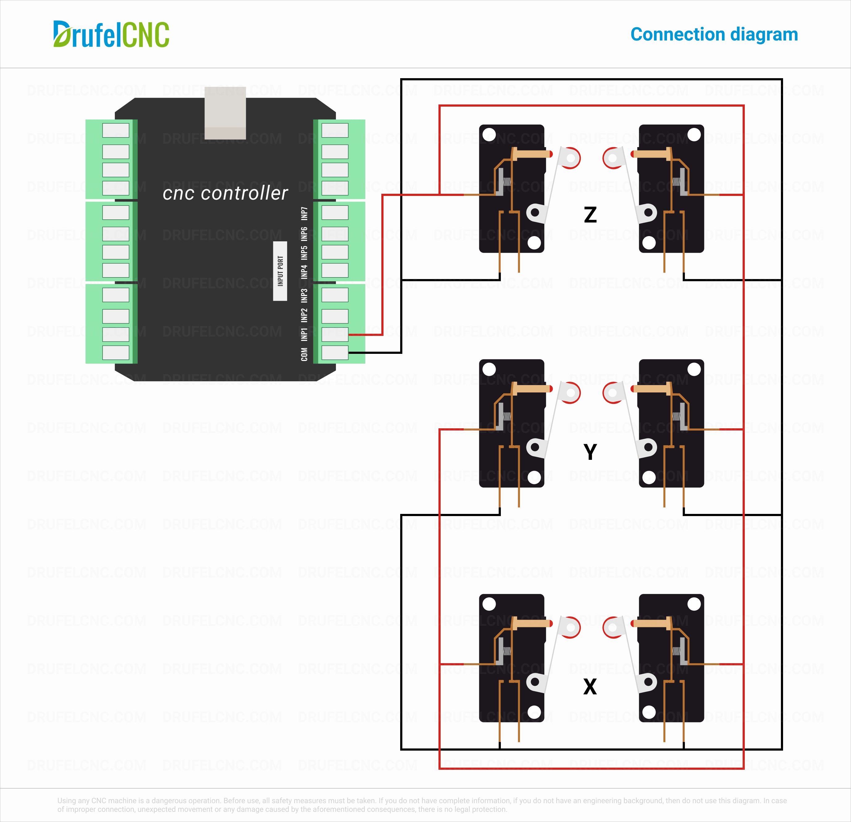
When choosing a circuit for connecting the limit switches, you must be guided by the number of free input ports of your CNC controller. Also limit switches can be connected in parallel or in series.
Parallel connection diagram of limit switches using 1 input port.

Serial connection diagram of limit switches using 1 input port.

Parallel connection diagram of limit switches using 3 input port.
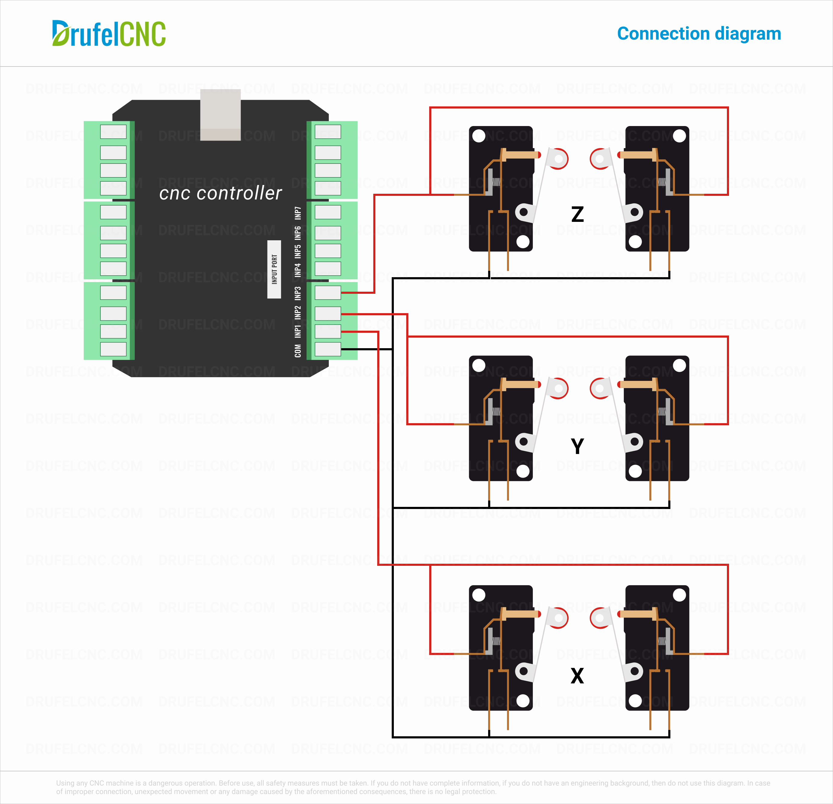

Serial connection diagram of limit switches using 3 input port.
Parallel connection diagram of limit switches using 6 input port.
Serial connection diagram of limit switches using 6 input port.